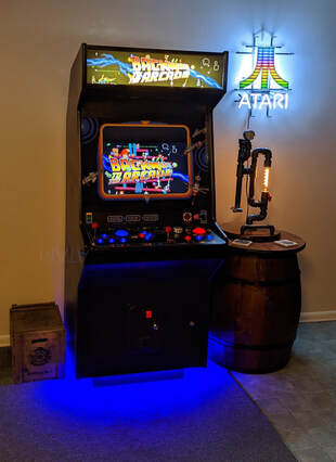

 Control Panel with Lights It's not enough to just have a cool control panel, we also need lighting. I discovered that there are some lighting kits out there but I figured I could do it for less money; and I did. I was fortunate to have a local electronics store where I purchased some 'wearable' LED's which were the basis for my lighting system. I made some bases from polystyrene sheet and glued the LED's to them. While my control panel was in this 'portable' configuration I just hooked up 2 D-cell batteries to power the lights. Continue to Part 5 - Research Intro | The Games | Control Panel Configuration | The Controls | Control Panel Lights | Research | Specific Games | Hardware & Software | Game Configurations | Cabinet Build | Artwork | Bonus | Leaderboard | Summary
0 Comments
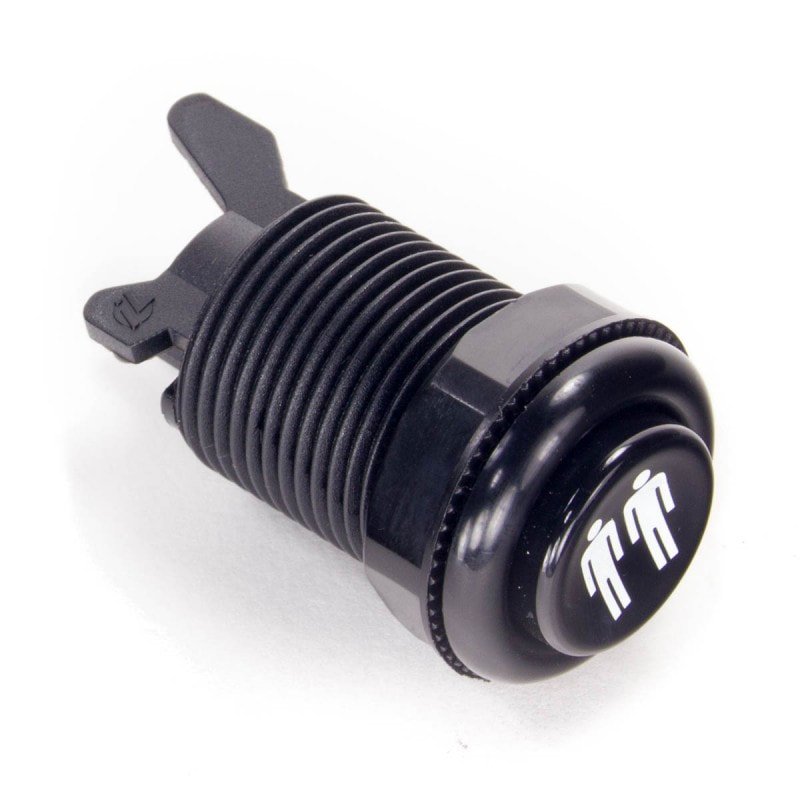
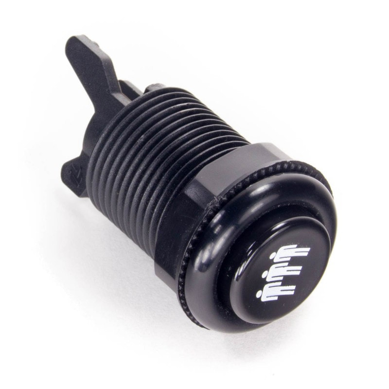
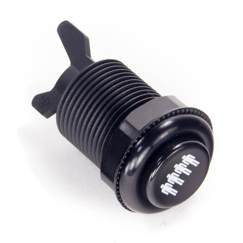
 After many years of tinkering and configuring changes I still didn't have the space for an arcade cabinet, but there was no reason that I couldn't build a real arcade control panel that would connect to the TV for somewhat authentic game play. So I made the decision to build a real control panel. In January 2017 I put together a list of controls that I would need and made an order! Actually I made a few orders. All of the controls and the keyboard encoder came from Ultimarc and the buttons came from Paradise Arcade Shop and Focus Attack because Ultimarc did not stock the concave style translucent buttons that I wanted. I also had a hard time finding Player 3 and Player 4 buttons which were needed primarily for 2 more of my favorites, Track & Field and Hyper Sports. Up until this point I thought I was going to run this system from an old PC or laptop (I had plenty of those laying around) but my daughter, the one who was 5 years old when I started this venture was now 23 years old and quite the techie suggested that I use a Raspberry Pi for this project. At first I was a bit reluctant to go through a new learning curve but as I did a little research it made a lot of sense, so that is what I did. I'll be discussing a bit more about the Raspberry Pi and the operating system, Retropie in a later chapter.
Another benefit to the 4/8-way joysticks is that I can now add Q*bert and Congo Bongo to my collection because when the joysticks are configured as 8-way they work great as diagonal 4-way sticks for these type of games.
A discussion about controls wouldn't be complete with out talking about the keyboard encoder. This is actually the heart of the control system. I went with the Mini-PAC Opti which is an Integrated Switch/Joystick/Trackball/Spinner interface. Since my setup has 2 trackballs, I also used a U-HID Nano to connect my second trackball.
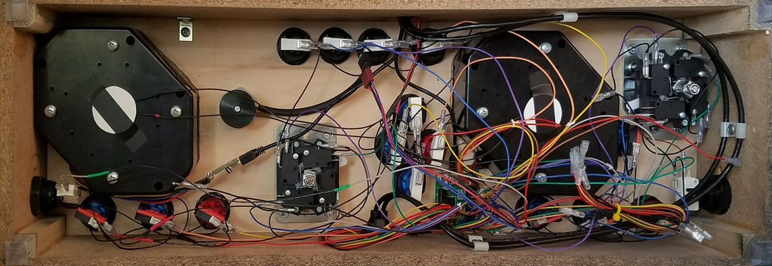 Control Installation and Wiring 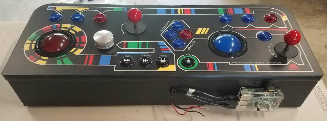 Final project with Raspberry Pi installed on the back of the panel housing Continue to Part 4 - Control Panel Lights Intro | The Games | Control Panel Configuration | The Controls | Control Panel Lights | Research | Specific Games | Hardware & Software | Game Configurations | Cabinet Build | Artwork | Bonus | Leaderboard | Summary
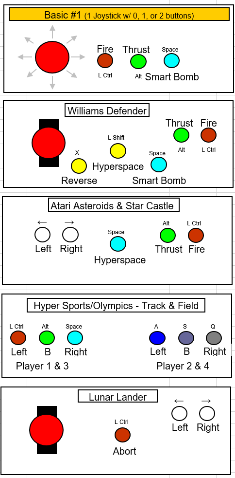
In the last section I talked a lot about the controls for the various games and how they cannot be properly replicated through a keyboard. In this section I am going to discuss the control panel configuration that I chose to maximize the amount of games that I could play. I already mentioned Defender which is one of the games I really enjoyed as a teen. The only problem was that my quarter didn't last too long because I never really got very good at it. There are some games that I can distinctly remember the place that I played them the most. In the case of Defender, it was a place called Magic Carpet Golf, a miniature golf and arcade in South Lake Tahoe, CA. This is a place that I frequented with my friends in the early 1980's.
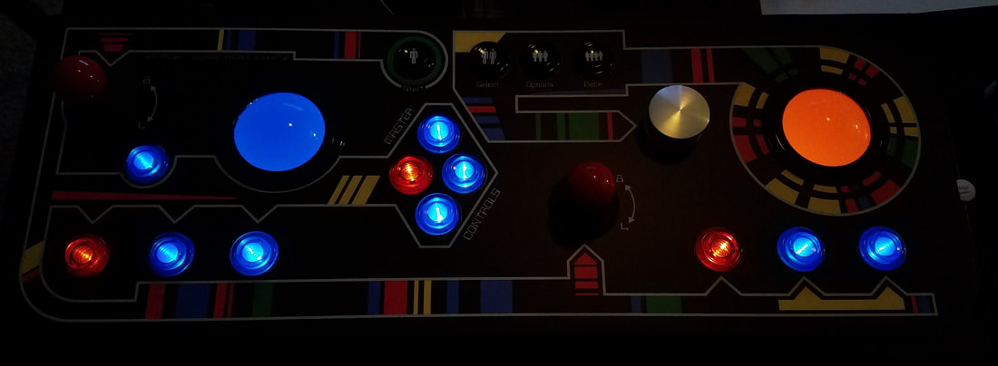
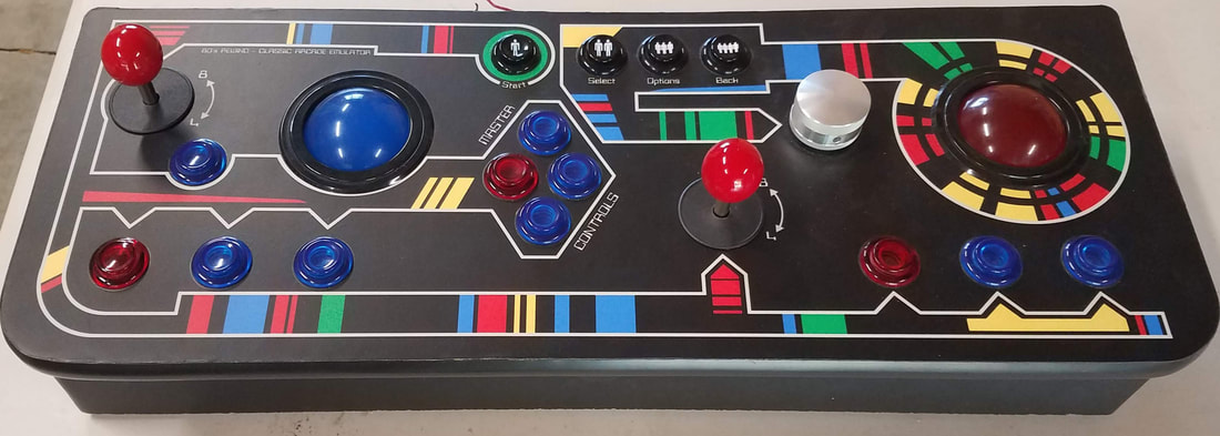
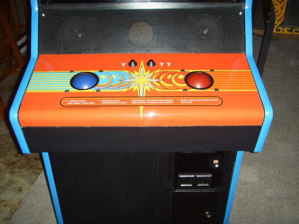
The years went by and I continued my research off and on. Throughout that time I continued to collect ROM's of games that I remembered in my youth. As I remembered games, I had to re-think the layout of my future control panel which went through many iterations. One of my later renditions is shown below. This configuration would allow reasonable game play for many of my favorites. 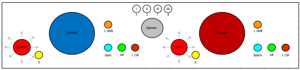 Early control panel configuration layout Up to this point I had been using Microsoft Excel and the drawing tools to sketch out my potential layouts. That would change once I decided to tackle Photoshop. I went through many iterations until I finally settled on the following as my permanent layout. This final layout and design was largely inspired by the Defender panel art and maybe a little subliminal inspiration from the LCARS computer system in the Star Trek universe. 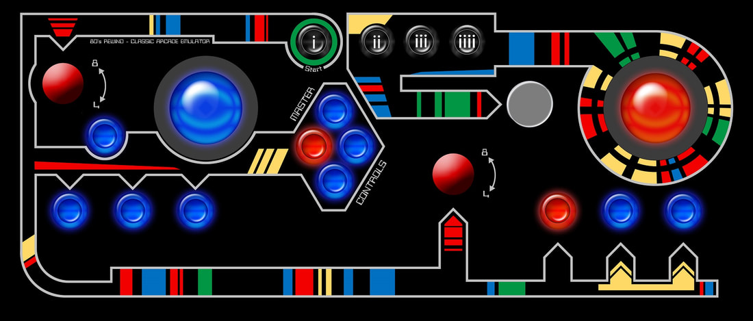 Defender inspired panel art Continue to Part 3 - The Controls Intro | The Games | Control Panel Configuration | The Controls | Control Panel Lights | Research | Specific Games | Hardware & Software | Game Configurations | Cabinet Build | Artwork | Bonus | Leaderboard | Summary
It's all about the games, isn't it? Or is it? Well that's just the beginning of the story. The games are fun but the complete experience is missed without proper sights, sounds, and controls. In order to replicate the 'real' experience we have to build a cabinet and get realistic controls for the games.
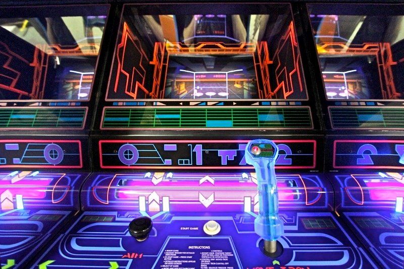
So far, I have only talked about games with a 'standard' control panel (joystick and buttons). There are also many games that use a driving wheel and pedals such as Pole Position and Night Driver, or a flight yoke/stick with buttons, or games that used spinners like Tempest or Tron. We've just eliminated a few more classes of games that cannot be played on a keyboard.
I've been talking a lot about controls, so I guess that is going to be the next section. But before I do that, I'll continue talking about the games. My preference were the games from the late 1970's through the mid 1980's like some that I have previously mentioned. I was also able to get the LaserDisc games working such as Dragon's Lair and Space Ace. I remember when Dragon's Lair hit the arcades in 1983; it was unlike any video game we had ever seen. Personally I thought it was quite incredible due to the graphics, but I never got any good at it because it was double the price, $0.50 (too rich for my blood) and I was lucky to last 30 seconds after the intro. I had a friend that discovered the patterns pretty quickly and used to just watch him play. The LaserDisc games didn't really catch on. I'm not sure if it was due to the video game crash of 1983 or just not the best medium for games. We may never know.
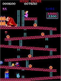
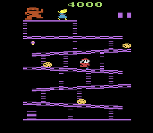
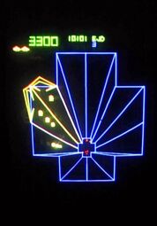
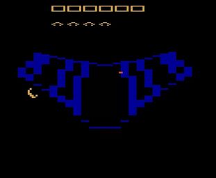
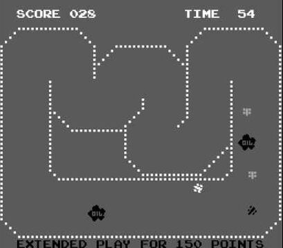
Continue to Part 2 - Control Panel Configuration Intro | The Games | Control Panel Configuration | The Controls | Control Panel Lights | Research | Specific Games | Hardware & Software | Game Configurations | Cabinet Build | Artwork | Bonus | Leaderboard | Summary 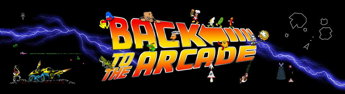 Back to the Arcade - An IntroductionAfter nearly 20 years in the making, I have finally finished my classic arcade cabinet. Somewhere around 1999 I discovered that I could play classic arcade games such as Donkey Kong, Pac-Man, Defender, Centipede, and many, many more on my PC. For me, these classic games were a lot more fun than the current games found in the more 'modern' arcades. Once I discovered that these were essentially the exact same games I played during my teenage years (including the coin drop) I was hooked by a bit of nostalgia. Throughout my early teen years I wanted these games in my home and tried to replicate the experience through my Atari VCS (2600), then via a Commodore VIC-20, then to the Commodore 64, and finally through my Commodore 128. Unfortunately the games on those platforms just didn't quite satisfy my desire for the authentic arcade experience. I'm not just talking about the physical cabinet and controls, I'm mostly referring to the graphics. Check out these examples...
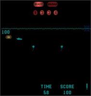
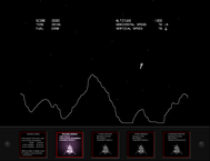
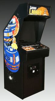
For a really good comparison of the different systems, check out Let's Compare Classic (Donkey Kong) on YouTube. During the research process I even re-discovered some games that I had forgotten about and played even before the video game craze started with Space Invaders, Asteroids, and Pac-Man. These were games such as Sprint One, Sea Wolf, and Lunar Lander which were all begging for my quarters when our family used to go to the local Straw Hat Pizza in South Lake Tahoe. I will discuss more about these specific games later and why they are special.
This blog, which is broken up into multiple parts will document the process that I went through to get to my finished project that I call, 'Back to the Arcade.' Click the links below to continue the journey. Enjoy! Continue to Part 1 - The Games Intro | The Games | Control Panel Configuration | The Controls | Control Panel Lights | Research | Specific Games | Hardware & Software | Game Configurations | Cabinet Build | Artwork | Bonus | Leaderboard | Summary
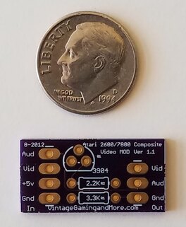
 So I've completed the repairs to my VCS and now ready to bring it into the 21st century by installing a composite video modification and removing the antiquated RF system. Once again, I found a good video on the topic from ArcadeUSA where I got the information on where to purchase the parts. I purchased the parts kit from Vintage Gaming and More! but through their Ebay outlet which saved me a few bucks. The kit is $12.99 + $2.00 shipping directly from their site, but I found it on Ebay for $9.99 and free shipping (plus I had a $3.00 coupon somehow so I got it for a total of $6.99 shipped). In case you haven't ready my prior post titled Atari 2600 (VCS) Repairs, my unit is a 'Light Sixer' unit which has 2 boards and the following instructions are for this unit only (the 4-switch units have only 1 board and are similar but have components in different locations). Just like my last blog, My instructions assume that anyone attempting this repair knows how to remove the boards from the case so I will not go into that here. I am also assuming basic soldering/de-soldering skills. Main board modificationsModification #1 - Remove the transistor at location Q202. This can be done by either cutting the transistor right off the board or de-soldering it. Modification #2 - Remove the resistor at location R213. Like the transistor, this can be done by either cutting the transistor right off the board or de-soldering it. 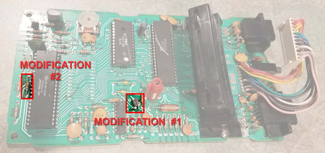 switch board modificationsModificaton #1 - Remove the RF modulator circuit board. Optionally you can remove the entire RF modulator assembly as I did. This makes for a cleaner modification and allows space for the new modification board. The important thing is that you remove the 5 pins of the RF modulator circuit board from the switch board. These pins can be cut or de-soldered but note that 3 of the 5 holes will need to be open to install the modification parts. If you opt for the de-solder method, note that intermediate de-soldering techniques will be needed. 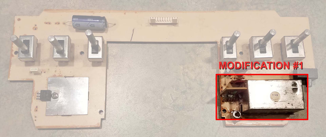 Composite video circuit board
After the components are soldered to the board, it is time to solder the wires to the board. The kit comes with 2 short lengths of 4-conductor wire. Pull the yellow wire out of one of the sheathings to make it a 3-conductor. Next, layout the assembled board and determine where it will be mounted so you can determine wire lengths. Following is a picture of how I mounted mine. 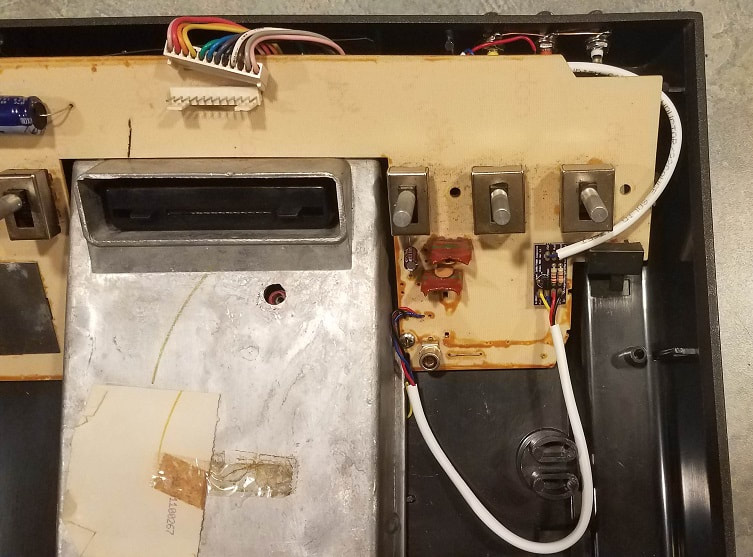 Composite Video Circuit Board Installation Suggestion 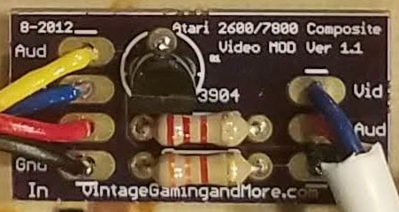 Assembled Composite Video Board 4-conductor wire installation - the switch board end of the wire will be installed in 3 of the 5 holes previously occupied by the RF Modulator Circuit Board. If looking from the top down, the wires will be installed in holes 1 (black), 3 (red), and 4 (blue). The 4th, yellow wire will be soldered to the bottom of the main board in an open hole connected to C210. The reason it has to be installed from the bottom is due to the way the metal case fits on the main board. A small notch will have to be made on the bottom of the metal case to allow access for the yellow wire (see picture). I used a rat-tail file to accomplish this, but a Dremel tool would work as well. Make sure there are no sharp edges otherwise future shorting may occur. 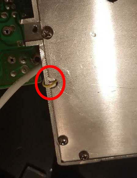 3-conductor wire installation - before the wire installation, 3 holes need to be drilled into the rear of the housing. To do this, I recommend a stepped drill bit since they tend to work better on thin materials such as the 2600 housing. 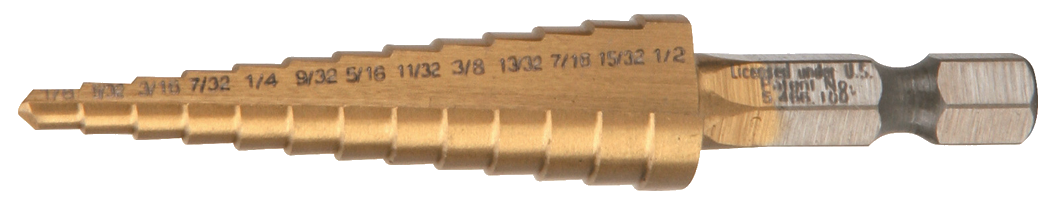 Stepped Drill Bit I chose an installation location just above where the original RF cable exited the housing. The best way I have found to get equal and level spacing for the holes is to place a piece of masking tape where the holes are to be drilled and carefully mark the hole locations. I spaced them 2 cm apart to allow room for the cable ends to install without interference. 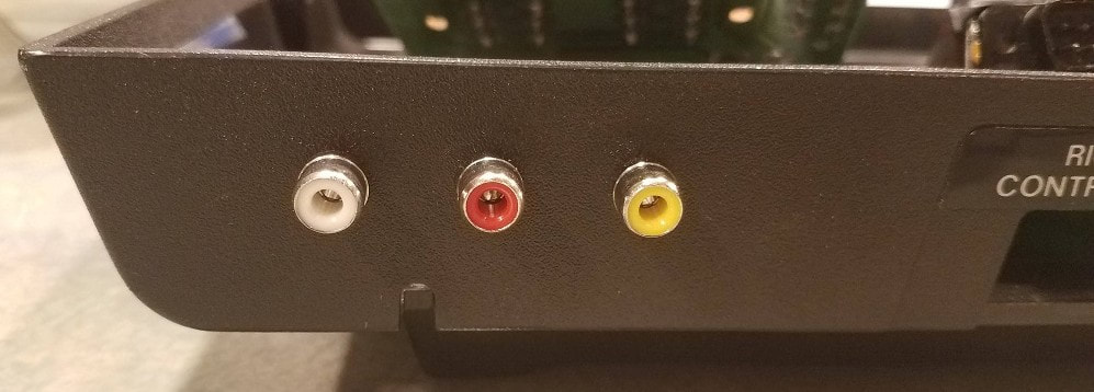 RCA Jack Locations Before installing the RCA jacks, I suggest measuring and soldering the black wire to the 3 solder rings. This can be done after installation, but proves to be a bit more difficult since they are right next to the plastic and quite a bit of heat is required to solder these. 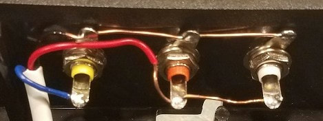 Once the solder rings are done, install each of the jacks with the solder ring going on first, then the lock washer, then the nut. Now solder the red wire to the red and white (audio) jacks and solder the blue wire to the yellow (video) jack. summaryNow put it all back in the case and enjoy. In the end, I spent a total of $57.85 to get a working Atari 2600, plus learned some new skills along the way.
I already had some joysticks and paddle controllers from another project (blog coming soon) and had also picked up a Combat cartridge at an arcade expo for $2 so now I guess it is time to start collecting cartridges of my favorite games!  As a kid, I grew up on the Atari VCS system (more commonly known as the Atari 2600). I was fortunate that my Dad owned a hobby shop/toy store when this came out in 1977 and was one of the first of my friends to have one (along with many of the games that play on it). In 1985 when I was departing for my time in the Air Force I was unloading a storage unit of my things and the truck driver was very interested in my Atari so I gave it to him making for one very happy family. Here I am over 30 years later and interested in retro-gaming so I picked up an old Atari VCS from a seller on Ebay a year or so ago not knowing the condition. The price was right for the gamble so I did it. As it turns out, it did not work (powered on but no picture) so I have been trying to decide what to do about it. One resource I found was at www.atari2600.com where they will repair any Atari 2600 console for $24.95 plus parts. I was considering this option but have always wanted to tackle a small-ish electronics repair job so I figured I would give that a try.
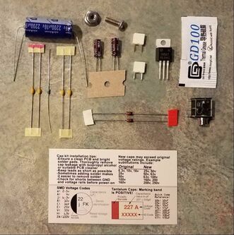
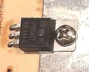
www.console5.com. Please note that this link goes straight to the kit for my 'Light Sixer' unit, there is another page with a kit for the 4-switch units. 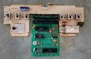 'Naked' Atari 2600 'Naked' Atari 2600 The 'sixer' units come with 2 boards, a main board and a switch board. I will be doing modifications to both of them. I did not get pictures of the boards before removing components, but it will be clear what I replaced. My instructions assume that anyone attempting this repair knows how to remove the boards from the case so I will not go into that here. Main board Repairs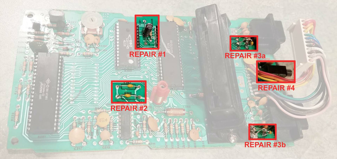 Atari 2600 Main Board NOTE In some cases I am using radial in lieu of axial type capacitors because that is what came in the kit. It does not make any difference for functionality but do be aware of polarity on these capacitors when installing.
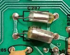
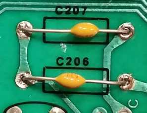
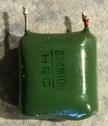
Repair #2 - Replace the original pair of styrene caps with 820 pF MLCC capacitors at locations C206 & C207. These capacitors are related to audio issues which I don't know if I have but since they are in the kit and I have all the soldering tools out I got them installed.
Repair #3 - Replace original diode/capacitor assemblies with new zener diodes and .1µF capacitors at locations C236 & C237. Solder the capacitor across each diode as shown in the picture. 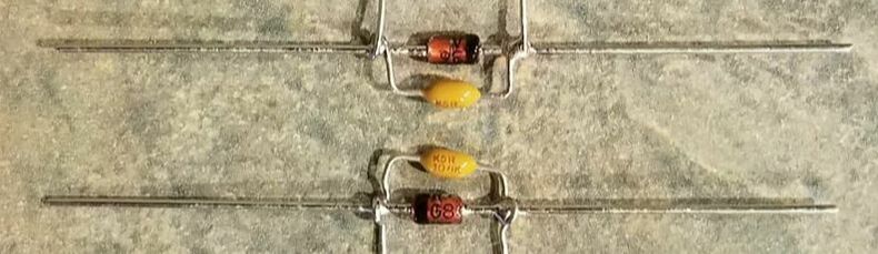 Repair #4 - Replace the DC Power Jack. They tend to get broken, dirty, or lose tension over the years. (no picture needed) switch board repairs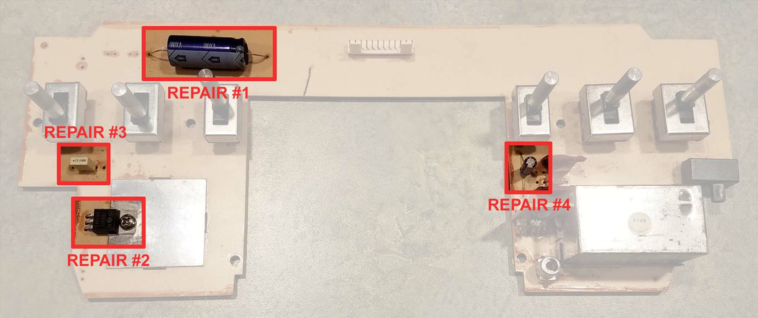 Atari 2600 Switch Board Repair #1 - Replace the original capacitor with a new 2200µF 16V axial type capacitor as shown. 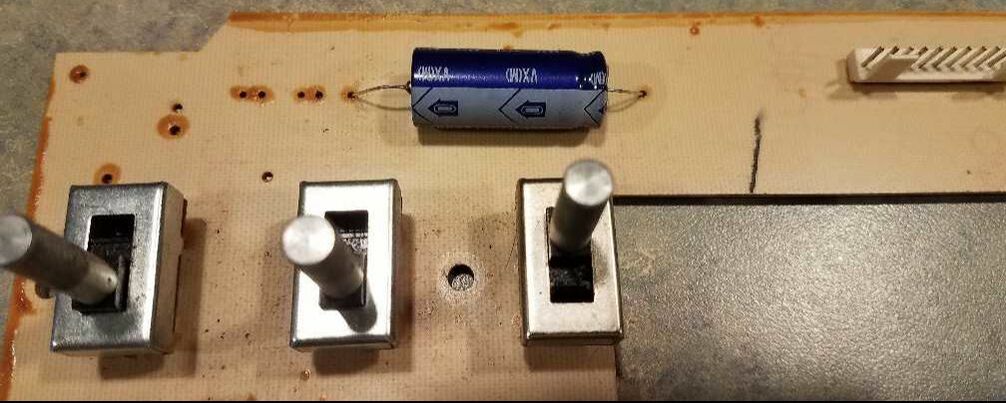
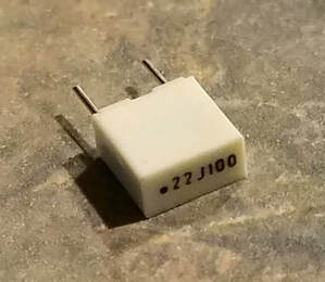
The repair kit even includes a bolt and nut for units that had the VR installed to the board via rivet. Fortunately mine was just a screw. Repair #3 - Replace the .22µF "chicklet" capacitor with a non-electrolytic type. The "chicklet" type sometimes cause 'sparkles' in the video when they fail.
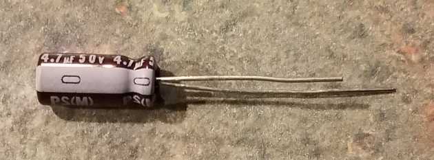
Repair #4 - Identical to repair #1 on the Main Board. Replace the original axial type capacitor with a new 4.7µF 50V radial type capacitor. Note polarity before removing old capacitor. summaryIn the end, this repair went quite well. Once I got all the components installed I was able to fire it up and have a working unit. 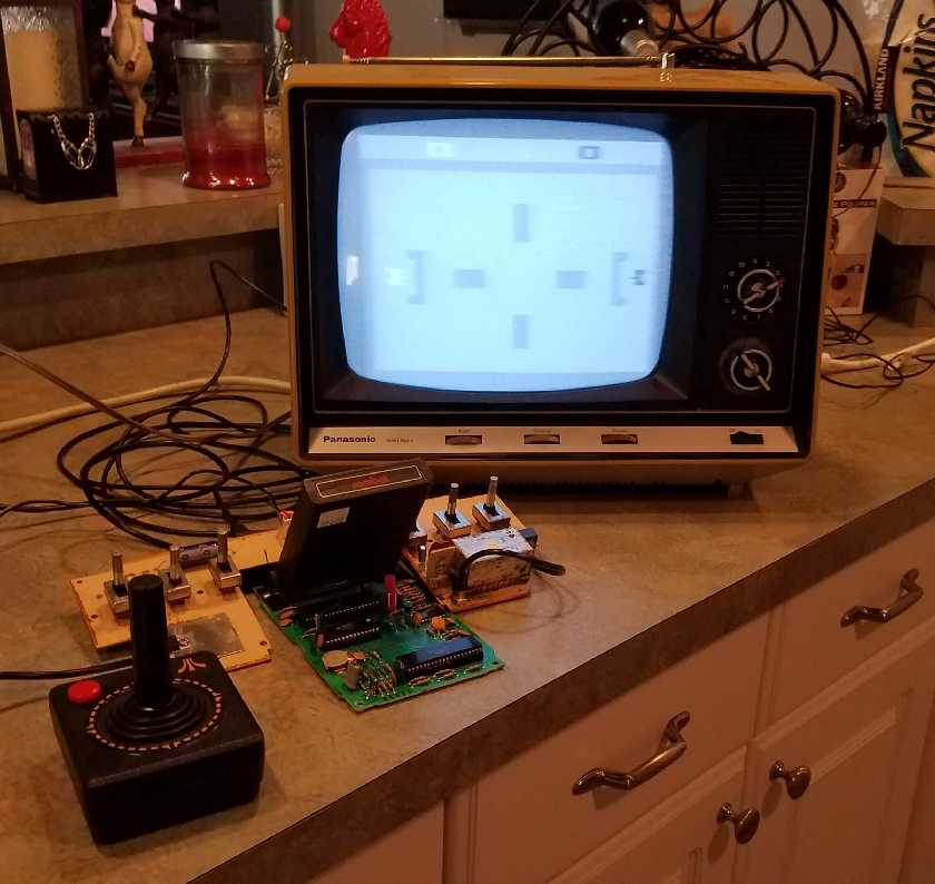 My next project will be installing a composite video modification to get better quality video and eliminate the RF modulator.
This modification can be made without removing the main shaft from the helicopter (as a matter of fact, it is better to leave it installed to get the proper length of the main shaft when trimming). Start by removing the main gear from the main shaft. Next using a 7/64" drill bit, carefully drill through the center of the main gear. Continue to enlarge the hole in 1/64" increments up to 7/32". Take care to ensure that the hole remains in the center of the gear. If is starts to get off-center, shave a bit off the 'thick' side with a #11 X-acto blade. Once the hole is 7/32" use the tapered reamer to enlarge the hole to a point where the one-way bearing (OWB) fits snugly in the hole. Place the bearing/gear assembly on top of the washer (to ensure proper clearance) and press down until the bearing is flush against the work surface and the main gear is flush against the washer. The side of the bearing with the washer thickness will be the top side so ensure that the OWB is properly oriented. Apply a thin bead of CA around the washer on both sides of the gear. Once the CA has cured, secure the gear/bearing assembly to the main shaft with a very small self-tapping screw that will thread into the main shaft without splitting the shaft.
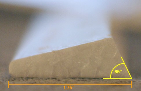
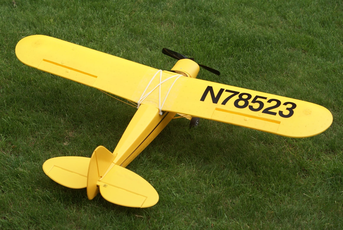
aileronsI purchased this kit since it is a trainer aircraft with optional floats so I can have something fun to fly off the water. The only thing that I didn't like is that it has no ailerons so I modified the wing to have ailerons. Each aileron is 9 inches long by 1-3/4 inches wide. I used a 65° cut on the leading edge of the ailerons to provide the clearance required for the 'up' movement. The parts I used are as follows: - Great Planes Small Nylon Control Horns (GPMQ3900) - DU-BRO Electric Flyer Hinge Tape (916) - Mini E/Z Connector (845) - Expert Electronics 6" Servo Y Harness (EXRA315) - 2 ea. Hobbico 12" Servo Extension (HCAM2100) - GWS Pico Servos
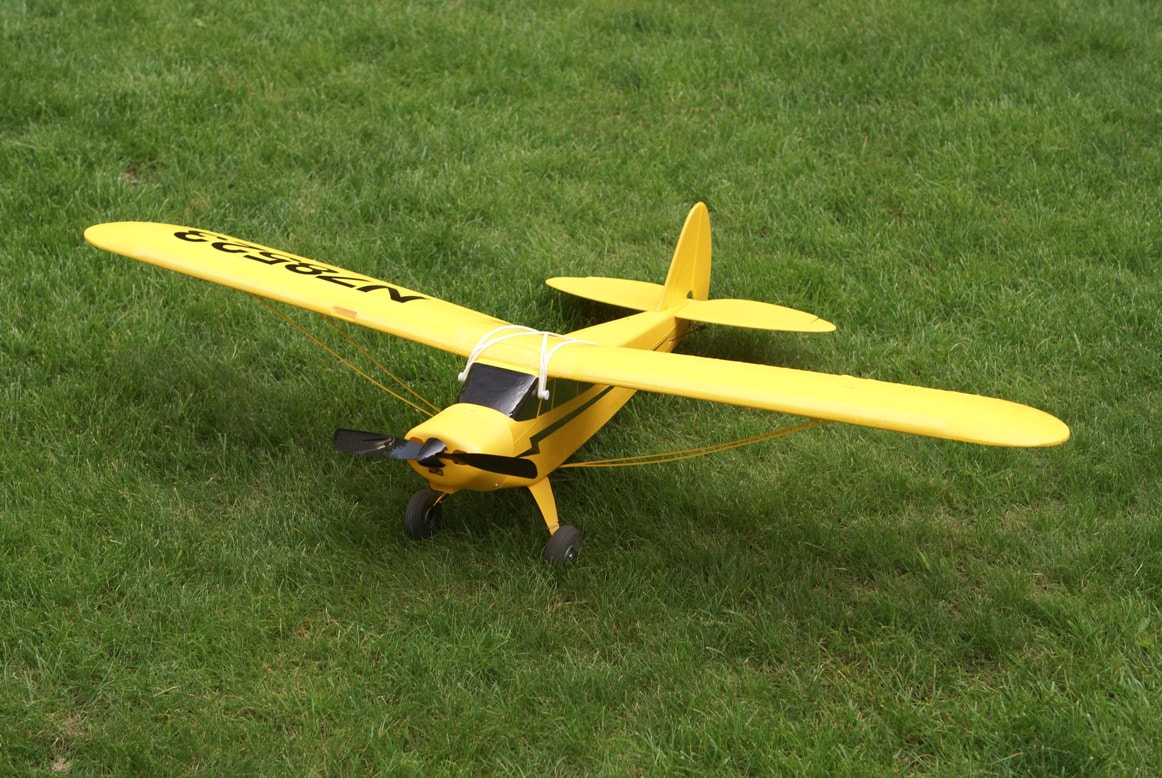
WheelsI went with the DU-BRO 2-1/2" Super Lite Wheels (250SL) to aid in take-offs and landings off the grass. The wheels are held on with 4-40 Lock Nuts (GPMQ3344). wing struts
reapirsWhen it becomes necessary to make repairs to the foam parts of the aircraft, I have found a great product for making repairs. Woodland Scenics Foam Putty 16 oz. (ST1447) My first repair was to a scuffed wingtip where approximately 1/4" of material was ripped off the wing tip. This product is very easy to work with and is quite easy to sculpt, carve, and sand. new paintAfter a couple years I decided to give this bird a new proper color for a Cub.
This modification uses an electroluminescent panel behind the LCD to provide the backlight. This is preferred to an LED lighting scenario due to the uniform lighting from behind as shown in the picture. I have created technical instructions which provide full color photographs to guide you through the whole process, as well as a list of parts and where to get them. Please contact me here if you would like to order a copy of the instructions for $5.00 or if you have additional questions. 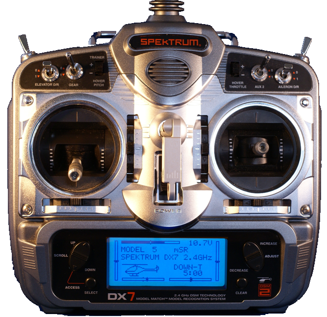 FAQs
Q: What format does the technical document come in? A: The document is delivered in an Adobe PDF format. Q: What is included in the price? A: The complete technical instructions to accomplish the modification, a parts list, and required tools list. Q: How much current does this modification draw? A: My configuration shown above was measured at 38 mAh. Q: How long will this modification take? A: This modification should take an average modeler about 2 hours to complete. Q: Do I need any special tools? A: Anybody that has been into modeling for any time at all should have all the tools necessary to complete the job. A soldering iron will be required. Q: Can I turn the backlight on and off? A: The modification that I completed does not include a switch , but I did include a schematic and switch part numbers if a switch is desired. Q: Will this modification void my warranty? A: I have not personally confirmed this with Spektrum, but I would expect that it does void your warranty. Q: How much will the parts cost? A: The parts for my modification cost $38.00 including shipping. Q: Can these instructions be used for other models of transmitters? A: Although I have not modified another type of transmitter, you should be able to modify any LCD display that is accessible from the back side. |
Dan BlanchardThis is my collection of tips, tricks, and projects that I have made over the years while enjoying my various hobbies. Categories
All
Archives
July 2020
|


 RSS Feed